What is a grid?
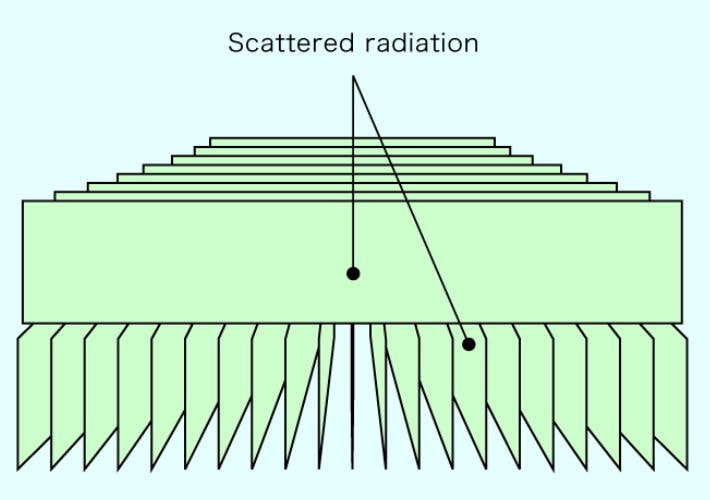
When the primary radiation passes through a subject during X-ray imaging, scatter radiation is inevitably produced, caused by various substances in the subject. When scatter radiation reaches the film, it sensitizes even areas which should not be sensitized. This produces radiographic fog on the film and lessens contrast, which degrades the diagnostic quality of the X-ray. A grid, the formal name of which is Anti-Scatter Grid, acts as a filter, effectively removing scatter radiation before it reaches the film.
IEC60627/Ed.3 (Diagnostic X-ray imaging equipment - Characteristics of general purpose and mammographic anti-scatter grids) strictly specifies the test procedure to obtain the physical characteristics such as Grid Exposure Factor (B), Grid Selectivity (Σ), Contrast Improvement Ratio (K) and Image Improvement Factor (Q).

Grid structure
A grid is composed of high X-ray transmitting material and high X-ray absorbing material, each aligned alternately and regularly. MS X-Ray Grids use aluminum or fiber strips with a thickness of 0.1 - 0.25 mm as transmitting material and lead strips with a thickness of 0.020 - 0.050 mm as X-ray absorbing material.
These strips are laminated, baked and solidified. Then the surface of the laminated board is smoothed uniformly and the ratio is fixed. After the ratio is fixed, the board becomes the inner substance of the grid and is then covered and finished. MS X-Ray Grids are carefully inspected several times and tested under clinical conditions to ensure precision and quality.
Inter-spacer Material
Aluminum or fiber resin is mainly used for the inter-spacer; synthetic resin is applicable as well. Wood was often used as inter-spacer material in the past.
We are often asked about “Carbon Fiber Grids”. We believe that it is impractical to use carbon fiber as inter-spacer material since it is difficult both to process and to control the uniformity of thickness. The attraction of carbon fiber is its low absorption character. With regards to this important characteristic, carbon fiber is used as the cover material for MS X-Ray Grids.
Grid Specifications
Density (Strip Frequency)
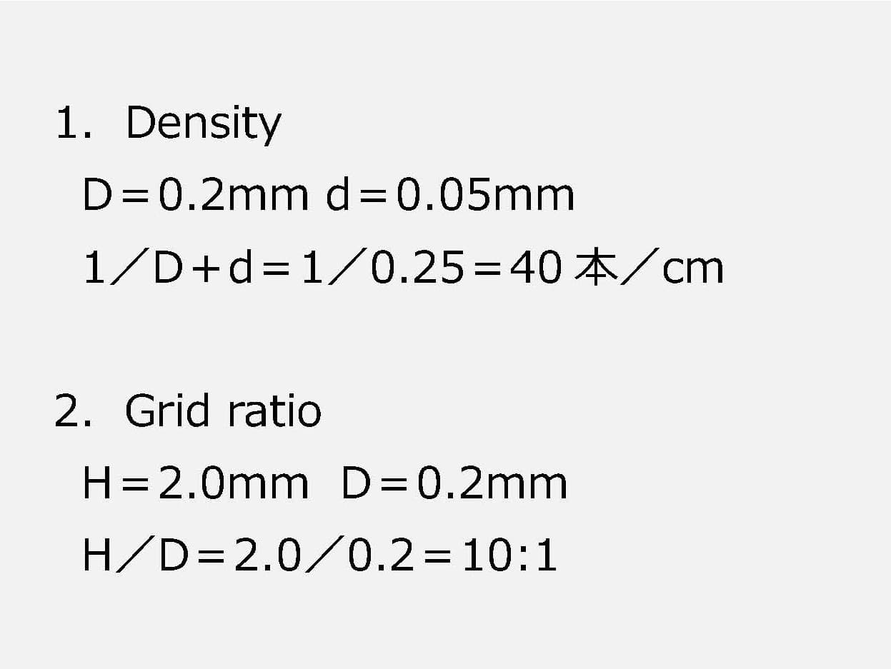
This refers to the number of X-ray absorbing strips per 1 cm (Fig.1). MS X-Ray Grids are available in densities of 34, 40, 60, and 80 lines per 1 cm as standard specifications. The higher the grid density, the better the film image, with less visible gridlines. When grid line elimination software is used during Flat Panel Detector (FPD) imaging, precise low density grids, such as the 40 line/cm grid, are popular choices. High density grids, such as the 80 line/cm grid, are useful for imaging without grid line elimination software. In addition, we are able to offer customized density which fits the pixel pitch of each FPD system.


Grid Ratio
Simply speaking, grid ratio is the thickness of the grid (Fig.1). The thicker the grid is, the sharper the film image becomes, but the lower the x-ray transmission is. Therefore, in cases of high X-ray output (voltage), a higher ratio (thicker) grid is used. In cases of low X-ray output, a lower ratio (thinner) grid is preferred.
3:1 to 6:1 ratio grids are recommended for low X-ray output and ratios over 8:1 are recommended for high X-ray output. We offer a range of ratios from 3:1 to 16:1 as standard specifications.
Focusing
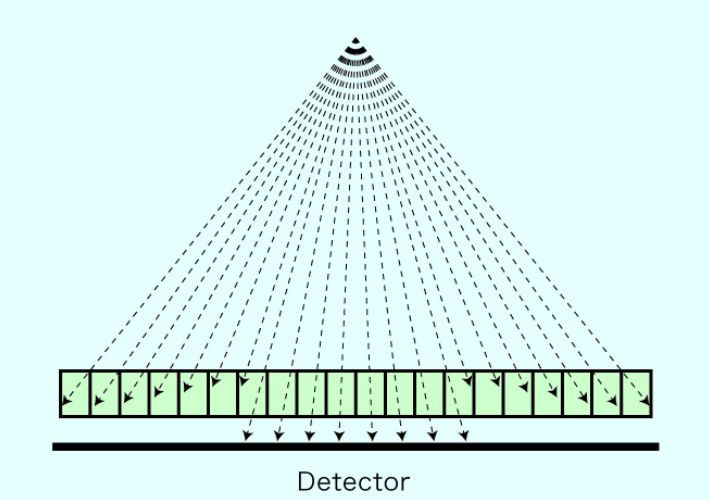
This is the distance from the X-ray tube to the incident face of the grid. It is ideal to use a grid having the proper focal distance complying with the radiographic distance. If a grid with a different focal distance from the actual radiographic distance is used, part of the primary radiation which is necessary to create the film image is also absorbed along with the scatter radiation, producing a film image with insufficient exposure.

MS X-Ray Grid Selection
Recommended Specifications
| Use | Denseity | Ratio | FFD | 備考 |
| Neck | 40L/cm | 8:1 | 120cm | At 70Kv |
| Chest | 40L/cm | 10:1 | 200cm | At 120Kv |
| Stomach | 40L/cm | 8:1 | 100cm | At 90Kv |
| Both chest and stomach | 40L/cm | 8:1 | 150cm | Chest 180cm (F2) Stomach 120cm (F1) |
| Both orthopedic and chest | 40L/cm | 8:1 | 120cm | Chest 150cm (F2) Orthopedic 100cm(F1) |
■ These are typical examples. Changes can be made to suit each case.
■ If one grid is used for 2 purposes, F1/F2 should be +/-30cm.
Tips for chooseing density
When choosing a high quality grid, the most important thing to look for is precise focusing and uniform contrast.
Depending on the lead content rate, we recommend choosing a higher ratio when using a higher density grid.
For example, a 10:1 ratio is recommended at 60 lines/cm, and an 8:1 ratio is recommended at 40 lines/cm. The lead content rate is almost the same under both specifications.
Other Types of Grids
Parallel Grid
A parallel grid is a grid in which the planes of absorbing strips are parallel to each other and perpendicular to the incident face. Parallel grids are susceptible to the phenomenon known as cut-off. This is because the perpendicular absorbing strips shield not only scatter radiation but also primary radiation. When cut off occurs, high contrast is maintained at the center of the image, but the image becomes dull or blurry towards the edges. The smaller the actual distance between the tube and the grid is, the greater the cut-off becomes.
Parallel grids account for under 10% of all MS X-Ray Grids produced, but can be recommended for special cases such as imaging at great distances (over FFD200cm), and divided imaging. Parallel grids were more popular choices before the focused grid was developed.

Tips for Using Parallel Grids
The optimal focal film distance (FFD) for each grid is indicated on the label with the following mark: ∞.
As mentioned above, the cut-off phenomenon is unavoidable in imaging with parallel grids, and it is recommended that these grids be used only for imaging at great distances (over FFD200cm), divided imaging, and other special cases.
Cross Grid
A cross grid is a grid composed of two linear grids constructed in such a way that the direction of their absorbing strips form an angle. This type of grid is classified into two types: the Orthogonal Cross Grid in which the direction of the absorbing strips form a 90° angle, and the Oblique Cross Grid in which the direction of the absorbing strips form an angle of other than 90°.

Long Size Grid
Long size grids are used for wide view imaging such as full leg and full spine.
Long size grids are produced by combining several conventional sized grids whose strips are connected precisely in the same direction. The connected inner substances are then covered with an aluminum cover and painted. As a result, the wide view image appears fully connected.
Mitaya is able to provide long size grids with the following specifications: 60 lines/cm 8:1-14:1 ratio, 40 lines/cm 6:1-8:1 ratio, and 34 lines/cm 5:1-12:1 ratio, in sizes up to 400 x 1095mm. We strongly recommend the “Cap-type” or “With Frame” options to protect such long size grids.
[Ex.] 10 x 36: Three 10 x 12 grids are connected. (2 connections)
Mammographic Grid
A Mammographic Grid is a focused grid designed specifically for mammography.
Potential Image Problems
Cut-off
Cut-off, in which the image becomes dull or blurred towards the edges, occurs when the focal film distance (FFD) is set contrary to the FFD indicated for each grid. This is a particular risk with parallel girds.
An application limit is assigned to each grid, according to each grid's individual specifications. This application limit shows the range at which FFD can be adjusted which will limit cut-off to 40% or less.
The use of “Bucky” introduces further potential complications that may result in cut-off. This is due to the horizontal motion of the grid that occurs when “Bucky” is employed.
We strongly recommend that FFD be set within the application limit indicated for each grid to ensure the best possible image quality.
Ununiformity of Image
Ununiformity of image, generally referred to as “Moire”, is a fringe image that sometimes occurs due to the difference between grid density and the pitch of the scanning lines of the detector. As this difference becomes smaller, the fringe image becomes larger.
CR
The scanning lines in Computed Radiography (CR) are linear. The easy way to eliminate “Moire” is by setting up the CR system and the X-ray grid in an orthogonal orientation. In addition, adjusting the grid density and/or the pitch of the scanning lines of the CR system, and setting the grid in a tilted direction against the scanning lines are both effective means of eliminating “Moire”.
FPD
The scanning lines of Flat Panel Detectors (FPD) consist of pixels. “Moire” appears and becomes larger depending on the difference between the pixel pitch and the grid lines. The frequency of this difference causes visible “Moire”. Recently, “Moire” eliminating software is commonly used, so it is important to choose a grid density recommended by the FPD manufacturer.
Crosswise Difference of Image
The major cause of crosswise difference of image is mis-alignment between the X-ray tube and the grid surface. When this problem occurs we recommend having the system checked to ensure that the alignment is correct.
However, crosswise difference of image is sometimes the result of grid deformity due to long-time use. To determine if this is the cause of the problem
, we recommend this simple test: Create two images, one in the regular position and another in an up-side down position. If the problem appears symmetrically, it is likely a problem with the grid.
Pixel Aligned Grid
The Pixel Aligned Grid is a super precise grid capable of creating a higher quality image.
The pitch of the grid-line is aligned with the pixel pitch of FPD at a tolerance within 0.5μm (5/10000mm), and it ensures maximum reduction of moire.
And, this alignment of grid-line pitch and pixel pitch results in a superior transmission rate of primary radiation when compared to conventional grids, creating a sharoer image.
The Pixel Aligned Grid is useful for radiography involving thin body parts.
